5. Application of Ordinary Differential Equations: Series RL Circuit
RL circuit diagram
The RL circuit shown above has a resistor and an inductor connected in series. A constant voltage V is applied when the switch is closed.
The (variable) voltage across the resistor is given by:
`V_R=iR`
On this page...
Time constant
Two-mesh circuits
RL circuit examples
Two-mesh circuits
The (variable) voltage across the inductor is given by:
`V_L=L(di)/(dt)`
Kirchhoff's voltage law says that the directed sum of the voltages around a circuit must be zero. This results in the following differential equation:
`Ri+L(di)/(dt)=V`
Once the switch is closed, the current in the circuit is not constant. Instead, it will build up from zero to some steady state.
Solving the DE for a Series RL Circuit
The solution of the differential equation `Ri+L(di)/(dt)=V` is:
`i=V/R(1-e^(-(R"/"L)t))`
Proof
We start with:
`Ri+L(di)/(dt)=V`
Subtracting Ri from both sides:
`L(di)/(dt)=V-Ri`
Divide both sides by L:
`(di)/(dt)=(V-Ri)/L`
Multiply both sides by dt and divide both by (V - Ri):
`(di)/(V-Ri)=(dt)/L`
Integrate (see Integration: Basic Logarithm Form):
`int(di)/(V-Ri)=int(dt)/L`
`-(ln(V-Ri))/R=1/Lt+K`
Now, since `i = 0` when `t = 0`, we have:
`K=-(ln\ V)/R`
Substituting K back into our expression:
`-(ln(V-Ri))/R=1/Lt-(ln V)/R`
Rearranging:
`(ln\ V)/R-(ln(V-Ri))/R=1/Lt`
Multiplying throughout by -R:
`-ln\ V+ln(V-Ri)=-R/Lt`
Collecting the logarithm parts together:
`ln((V-Ri)/V)=-R/Lt`
Taking "e to both sides":
`(V-Ri)/V=e^(-(R"/"L)t`
`1-R/Vi=e^(-(R"/"L)t`
Subtracting 1 from both sides:
`-R/Vi=-1+e^(-(R"/"L)t`
Multiplying both sides by `-(V/R)`:
`i=V/R(1-e^(-(R"/"L)t))`
[We did the same problem but with particular values back in section 2. Separation of Variables]
Here is the graph of this equation:
Graph of `i=V/R(1-e^(-(R"/"L)t))`.
The plot shows the transition period during which the current adjusts from its initial value of zero to the final value `V/R`, which is the steady state.
The Time Constant
The time constant (TC), known as τ, of the function
`i=V/R(1-e^(-(R"/"L)t))`
is the time at which `R/L` is unity ( = 1). Thus for the RL transient, the time constant is `\tau = L/R` seconds.
NOTE: τ is the Greek letter "tau" and is not the same as T or the time variable t, even though it looks very similar.
At 1 τ
`1-e^(-(R"/"L)t)`
`=1-e^-1`
`=1-0.368`
`=0.632`
At this time the current is 63.2% of its final value.
Similarly at 2 τ,
`1 - e^-2= 1 - 0.135 = 0.865`
The current is 86.5% of its final value.
After 5 τ the transient is generally regarded as terminated. For convenience, the time constant τ is the unit used to plot the current of the equation
`i=V/R(1-e^(-(R"/"L)t))`
That is, since `tau=L/R`, we think of it as:
`i=V/R(1-e^(-t"/"\tau))`
Let's now look at some examples of RL circuits.
Example 1
An RL circuit has an emf of 5 V, a resistance of 50 Ω, an inductance of 1 H, and no initial current.
Find the current in the circuit at any time t. Distinguish between the transient and steady-state current.
Answer
Method 1 - Solving the DE
The formula is: `Ri+L(di)/(dt)=V`
After substituting: `50i+(di)/(dt)=5`
We re-arrange to obtain:
`(di)/(dt)+50i=5`
This is a first order linear differential equation.
We'll need to apply the formula for solving a first-order DE (see Linear DEs of Order 1), which for these variables will be:
`ie^(intPdt)=int(Qe^(intPdt))dt`
We have `P=50` and `Q=5`.
We find the integrating factor:
`"I.F."=e^(int50dt)=e^(50t)`
So after substituting into the formula, we have:
`(i)(e^(50t))=int(5)e^(50t)dt` `=5/50e^(50t)+K` `=1/10e^(50t)+K`
When `t=0`, `i=0`, so `K=-1/10=-0.1`.
This gives us: `i=0.1(1-e^(-50t))`
The transient current is: `i=0.1(1-e^(-50t))\ "A"`.
The steady state current is: `i=0.1\ "A"`.
Method 2: Using the Formula
NOTE: We can use this formula here only because the voltage is constant. This formula will not work with a variable voltage source.
We have the following general formula:
`i=V/R(1-e^(-(R"/"L)t))`
So in this case:
`i=5/50(1-e^(-50t))` `=0.1(1-e^(-50t))`
Graph of the current at time `t`, given by `i=0.1(1-e^(-50t))`.
In this example, the time constant, TC, is
`tau=L/R=1/50=0.02`
So we see that the current has reached steady state by `t = 0.02 \times 5 = 0.1\ "s".`
Method 3: Using Scientific Notebook's Solve ODE
If you have Scientific Notebook, proceed as follows:
This DE has an initial condition i(0) = 0. We set up a matrix with 1 column, 2 rows.
For the answer: Compute → Solve ODE... → Exact
Example 2
A series RL circuit with R = 50 Ω and L = 10 H has a constant voltage V = 100 V applied at t = 0 by the closing of a switch.
Find
(a) the equation for i (you may use the formula rather than DE),
(b) the current at t = 0.5 s
(c) the expressions for VR and VL
(d) the time at which VR = VL
Answer
(a) We solve it using the formula:
`i=V/R(1-e^(-(R"/"L)t))`
We have:
`i=100/50(1-e^(-5t))`
`=2(1-e^(-5t))`
Graph of the current at time `t`, given by `i=2(1-e^(-5t))`.
(b) At `t=0.5,`
`i=[2(1-e^(-5t))]_(t=0.5)=1.8358`
(c) VR and VL are given by:
`V_R=iR `
`=2(1-e^(-5t))xx50 `
`=100(1-e^(-5t)) `
`V_L=L(di)/(dt) `
`=10d/(dt)2(1-e^(-5t)) `
`=100e^(-5t)`
(d) To find the required time, we need to solve when `V_R=V_L`.
`V_R=V_L` when
`100(1-e^(-5t))=100e^(-5t)`
`1-e^(-5t)=e^(-5t)`
`2e^(-5t)=1`
` e^(-5t)=0.5`
`-5t=ln\ 0.5=-0.69315`
So
`t=(-0.69315)/(-5)=0.13863s`
Substituting this value into VR gives:
`V_R=V_L` `=[100e^(-5t)]_(t=0.13863)` `=50.000\ "V"`
The graph of VR and VL is as follows:
Graph of the voltages `V_R=100(1-e^(-5t))` (in green), and `V_L=100e^(-5t)` (in gray).
The time constant, TC, for this example is:
`tau=L/R=10/50=0.2`
NOTE (just for interest and comparison): If we could not use the formula in (a), and we did not use separation of variables, we could recognise that the DE is 1st order linear and so we could solve it using an integrating factor.
We use the formula:
`Ri+L(di)/(dt)=V`
The required DE is:
`10(di)/(dt)+50i=100`
`(di)/(dt)+5i=10`
`"I.F."=e^(int5dt)=e^(5t)`
`ie^(5t)=10inte^(5t)dt=` `10/5e^(5t)+K=` `2e^(5t)+K`
Since `i(0)=0`, we have `K=-2`.
So `i=2(1-e^(-5t))`
It works :-)
Two-mesh Circuits
The next two examples are "two-mesh" types where the differential equations become more sophisticated. We will use Scientific Notebook to do the grunt work once we have set up the correct equations.
Example 3
In the two-mesh network shown below, the switch is closed at t = 0 and the voltage source is given by V = 150 sin 1000t V. Find the mesh currents i1 and i2 as given in the diagram.
Answer
We have not seen how to solve "2 mesh" networks before. We consider the total voltage of the inner loop and the total voltage of the outer loop. We then solve the resulting two equations simultaneously.
We use the basic formula: `Ri+L(di)/(dt)=V`
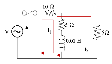
Considering the inner loop:
`10(i_1+i_2)+5i_1+0.01(di_1)/(dt)=` `150 sin 1000t`
`15\ i_1+10\ i_2+0.01(di_1)/(dt)=` `150 sin 1000t`
`3i_1+2i_2+0.002(di_1)/(dt)=` `30 sin 1000t\ \ \ ...(1)`
Now, considering the outer loop:
`10(i_1+i_2)+5i_2=150 sin 1000t`
`10i_1+15i_2=150 sin 1000t`
`2i_1+3i_2=30 sin 1000t\ \ \ ...(2)`
We now solve (1) and (2) simultaneously:
(1) × 3 − (2) × 2 gives:
`5i_1+0.006(di_1)/(dt)=30 sin 1000t`
Solving this using SNB with the boundary condition i1(0) = 0 gives:
`i_1(t)=-2.95 cos 1000t+` `2.46 sin 1000t+` `2.95e^(-833t)`
The graph of our answer is:
Graph of current `i_1` at time `t`. It's in steady state by around `t=0.007`.
Now, from equation (2), we have:
`i_2=1/3(30 sin 1000t-2i_1)`
`=1/3(30 sin 1000t-` `2[-2.95 cos 1000t+` `2.46 sin 1000t+` `{:{:2.95e^(-833t)])`
`=8.36 sin 1000t+` `1.97 cos 1000t-` `1.97e^(-833t)`
The graph of i2 is:
Graph of current `i_2` at time `t`. It's also in steady state by around `t=0.007`.
Example 4
The switch is closed at t = 0 in the two-mesh network shown below. The voltage source is given by V = 30 sin 100t V. Find the mesh currents i1 and i2 as given in the diagram.
Answer
We solve this 2 ways:
1. Setting up the equations and getting SNB to help solve them.
2. Directly using SNB to solve the 2 equations simultaneously.
Solution 1
We use the basic formula: `Ri+L(di)/(dt)=V`
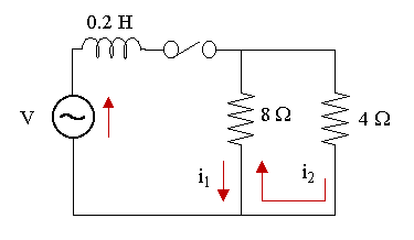
Considering the left-hand loop, the flow of current through the 8 Ω resistor is opposite for `i_1` and `i_2`. We regard `i_1` as having positive direction:
`0.2(di_1)/(dt)+8(i_1-i_2)=` `30 sin 100t\ \ \ ...(1)`
Now, we consider the right-hand loop and regard the direction of `i_2` as positive:
`8(i_2-i_1)+4i_2=0`
`12i_2-8i_1=0`
`i_2=2/3i_1\ \ \ ...(2)`
We now solve (1) and (2) simultaneously by substituting `i_2=2/3i_1` into (1) so that we get a DE in `i_1` only:
`0.2(di_1)/(dt)+8(i_1-2/3i_1)=` `30 sin 100t`
`0.2(di_1)/(dt)+8/3i_1=30 sin 100t`
Solving using Scientific Notebook gives:
`i_1(t)` `=-1.474 cos 100t+` `0.197 sin 100t+1.474e^(-13.3t)`
The graph of our solution is:
Graph of current `i_1` at time `t`. It's in steady state by around `t=0.25`.
Now, from equation (2), we have:
`i_2=2/3i_1`
`=2/3(-1.474 cos 100t+` `0.197 sin 100t+` `{:1.474e^(-13.3t))`
`=-0.983 cos 100t+` `0.131 sin 100t+` `0.983e^(-13.3t)`
This is of course the same graph, only it's `2/3` of the amplitude:
Graph of current `i_2` at time `t`. It's also in steady state by around `t=0.25`.
Solution 2 - Using SNB directly
If we try to solve it using Scientific Notebook as follows, it fails because it can only solve 2 differential equations simultaneously (the second line is not a differential equation):
`0.2(di_1)/(dt)+8(i_1-i_2)=30 sin 100t`
` i_2=2/3i_1`
`i_1(0)=0`
` i_2(0)=0`
But if we differentiate the second line as follows (making it into a differential equation so we have 2 DEs in 2 unknowns), SNB will happily solve it using Compute → Solve ODE... → Exact:
`0.2(di_1)/(dt)+8(i_1-i_2)=30 sin 100t`
`(di_2)/(dt)=2/3(di_1)/(dt)`
`i_1(0)=0`
`i_2(0)=0`
Exact solution is:
`i_1(t)=-4.0xx10^-9` `+1.4738 e^(-13.333t)` `-1.4738 cos 100.0t` `+0.19651 sin 100.0t`
` i_2(t)=0.98253 e^(-13.333t)` `-3.0xx10^-9` `-0.98253 cos 100.0t` `+0.131 sin 100.0t`
Note the curious extra (small) constant terms `-4.0xx10^-9` and `-3.0xx10^-9`.